Introduction
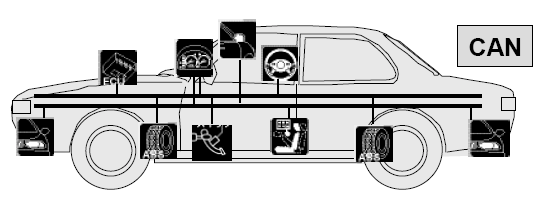
CAN (Controller Area Network) is a vehicle bus protocol standard which allows microcontrollers and ECU (electronic control units) to communicate which each other without a host computer. It is a message-based protocol, designed originally for multiplex electrical wiring within automobiles to save on copper, but can also be used in many other contexts. But why CAN you may ask, because it’s low-cost error less since via single CAN interface ECU can communicate with each through the centralized system with less wiring involved and data is transferred over digital signal instead of analog so it reduces chances of error occurrence. Also, it’s a tolerant system against electromagnetic noise which makes it best fit for vehicle electronics system.
There is another protocol which works on top of CAN called OBD (On-board diagnostics). OBD adds up the transport layer for CAN.

CAN vs. OBD vs. OSI layers
For physical layer CAN have two major standards to transmit data over a physical medium (wires)
- High Speed CAN Signaling. ISO 11898-2 (frequent error occurrence)
- Low-Speed Fault Tolerant CAN Network. ISO 11898-3 (less error occurrence)
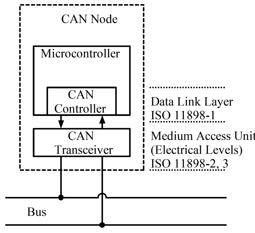
CAN node layout
I won’t provide more details of the standards above, because as IoT security researchers Data Link and Network layers are what we should be interested in. Let’s have look at standard CAN message frame format which gets transmitted over network.
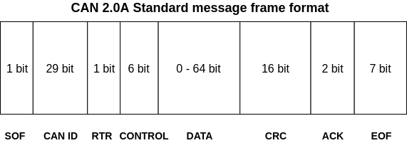
- SOF (Start of Frame): Tells other ECUs that message is incoming
- CAN-ID: Contains priority bits for message along with functional address of ECU (in terms of networking CAN-ID is like mac address, but not same thing)
- RTR: Remote transmission requests allows ECU to request messages from other active ECUs on network
- CONTROL: Informs length of the data in bytes
- DATA: Contains data values to be transmitted over protocol
- CRC: Cyclic Redudancy Values for error correction and data integrity
- ACK: It indicates status of CRC process
- EOF: End of frame marks the end of CAN message frame
Now for network packet forseics we only need to worry about CAN-ID, CONTROL and DATA
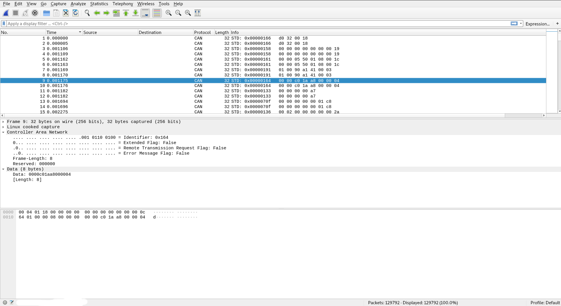
CAN-bus traffic in wireshark
As we can see in wireshark CAN-bus is event driven, when the data is generated by ECU via certain action (such as changing gears, indicators on/off, door lock/unlock etc.) it’s gets instantly broadcasted on network without any message sorting. So if we are looking for CAN-ID of specific ECU it becomes very hard to look through noise of data generated by other active ECUs in system. Thankfully linux got open source software suite called can-utils which allows us to create network interface for CAN traffic processing and sniffing. It has utility called candump which can display, filter and log CAN data to files.
Setting up virtual CAN network for experimentation and fun
So most of us are not brave enough to go out hook some hardware and mess around with actual vehicle but still want to know how CAN traffic acts in real time. Solution is ICSim (Instrument Cluster Simulator for SocketCAN) is simulator of vehicle Dashboard data over virtual CAN network.
Steps to compile ICSim
git clone https://github.com/zombieCraig/ICSim.git
apt-get install libsdl2-dev libsdl2-image-dev can-utils
cd ICSim && make && ./setup_vcan.sh
To start ICSim with default hardcoded CAN-IDs
./icsim vcan0
./controls vcan0
Now shorting changing data according to CAN-ID
cansniffer vcan0 #Any CAN interface of your choice
Select control window and press Up arrow key to increase speed, you will notice CAN-ID in cansniffer output changing value alot so that CAN-ID is for your vechicle speed data transmitted by engine ECU. You can also capture that traffic in wireshark and save it for further analysis. According to source code file icsim.c default arbitration/CAN-ID for speed data is 0x244.
Scapy recently added support for CAN protocol layer, so now you can all kind of data analysis in python. The basic script below saves all hex values from CAN-ID in array and finds of minimum and maximum speed. The more cool things can be done with matplotlib to create graph for speed data to know how many times vehicle got slow down due to road traffic.
from scapy.all import *
import struct

load_layer("can") #Allows us to work with CAN-bus network layer please note that it only works with latest veersion of ScaPy library

can_packets: rdpcap('canbus-traffic-capture.pcap')

CAN_ID: #Your desired CAN-ID for vehicle speed data in hex format
raw_data: []

for x in can_packets:
        if x["CAN"].identifier:= int(CAN_ID, 16):
            data: x["CAN"].data.hex()
            raw_data.append(data[10:]) #From traffic analysis we know that speed data only 4-bit long out of 14-bit hex string

raw_data: list(set(raw_data))

print("Raw RPM data in hex: " + str(raw_data))

delta_rpm: []

for y in raw_data:
    delta_rpm.append(int(y, 16))


print("Maximum RPM is: " + str(max(delta_rpm)))
print("Minimum RPM is: " + str(min(delta_rpm)))
There are more features in ICSim which allows you to increase difficulty with -r (randomized CAN-IDs) and -l options for learning. Since ScapPy supports CAN you can also write your own ICSim kind of utility in python as well. Check out ScaPy docs for CAN here.
For pentesting with external hardware such as RaspberryPi and Arduino you can order shield with MCP2515 controller